La primera opción sería encontrar la ubicación de las estaciones base celulares más cercanas. A veces esto es posible comprobando:
El sitio web de su operador; sin embargo, esta información generalmente no está disponible en sus sitios web ya que no necesariamente quieren revelarla a sus competidores. Consultar con su operador de red celular a través de su mesa de ayuda (o si tiene contacto con sus técnicos después de que se registró una llamada)
Inspeccionar el área en busca de estaciones base (torres o sitios en la azotea) con sus letreros puestos. Controlar https://opensignal.com/ u otras fuentes en Internet para obtener mapas de cobertura del área, los niveles de mayor intensidad de cobertura suelen ser donde se encuentra el sitio. Esto se puede seguir con una encuesta de esa área como se mencionó anteriormente.
Una vez que se determinan los sitios de estaciones base más cercanas, la antena se puede instalar en la dirección de esos sitios y se puede probar para cada escenario. Generalmente se prefiere el sitio más cercano o el sitio con línea de visión (LOS). Es mejor realizar la prueba en más de un sitio celular, ya que el sitio/LOS más cercano no siempre es el mejor debido al terreno, la interferencia, la capacidad/utilización, etc., ya que todos estos factores influyen en la estabilidad, la disponibilidad y el rendimiento de el enlace a la antena.
En situaciones en las que se desconocen las ubicaciones de los sitios de la red móvil celular y en las que las ubicaciones conocidas no proporcionan resultados suficientes, se puede seguir un proceso más iterativo realizando pruebas en todas las direcciones:
Apunte la antena hacia una dirección donde se espera cobertura (por ejemplo, la ciudad más cercana), o puede comenzar en una dirección conocida, por ejemplo, Norte. Pruebe el servicio y luego redirija la antena con incrementos de ángulo iguales y vuelva a realizar la prueba. Siga repitiendo esto hasta que se hayan probado las distintas direcciones, formando 360 grados completos. Tome nota de la intensidad y la calidad de la señal medidas en cada dirección.
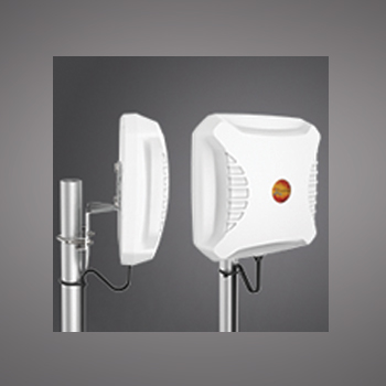
Para el LPDA-92 y XPOL-2 antenas, un intervalo de medición de 45 grados será suficiente. Esto significa que es necesario tomar medidas en ocho direcciones diferentes, por ejemplo, 0, 45, 90, 135, 180, 225, 270 y 315 grados. Para otras antenas, los intervalos de medición se pueden determinar a partir de sus patrones de radiación en azimut (horizontal) que se muestran en sus especificaciones técnicas.
Utilice el azimut de mejor rendimiento como línea de base e instale la antena en esa dirección (es posible optimizar aún más el azimut de la antena probando nuevamente a +20 grados y -20 grados desde esa posición, si es necesario).
Una vez completamente instalado; Pruebe nuevamente para asegurarse de que se logren los mismos resultados.
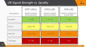
Puede realizar las mediciones de prueba mencionadas anteriormente con la mayoría de los enrutadores habilitados para 3G/LTE, que son capaces de informar la intensidad y calidad de la señal de la red celular, como RSRP, RSRQ, SINR, etc. (consulte la tabla a continuación).
El sitio celular tiene un nivel y calidad de señal mucho mejores. Por lo tanto, se recomienda reiniciar el dispositivo cada vez para asegurarse de que esté "bloqueado" el mejor sitio. Este puede ser un proceso un poco más lento, pero es una forma más confiable de determinar el mejor acimut.
También se pueden realizar pruebas de rendimiento, pero tenga en cuenta que los resultados de rendimiento dependen en gran medida de la red y de muchas influencias relacionadas con el ancho de banda/enrutamiento de Internet. Por lo tanto, las pruebas de rendimiento sólo deben realizarse con fines indicativos de qué rendimiento es posible y no para pruebas comparativas.
La ubicación de la antena en el edificio/local y su instalación es muy importante para garantizar el uso óptimo de la antena y, por tanto, el rendimiento de todo el sistema.
Aunque se aplica la regla general de instalar la antena lo más alto posible, desde una perspectiva de cobertura de RF; A veces es posible que la antena esté en un punto nulo (punto de cobertura débil) a esa altura específica. En este caso, la altura se puede ajustar para lograr el mejor servicio posible; en algunos casos, se encontró que una altura de instalación más baja lograba mejores resultados, pero esta no es la norma.
Las señales y la calidad de la red celular pueden fluctuar, a menudo entre 6 y 12 dB. Una medición que se toma ahora y unos momentos después puede diferir sustancialmente incluso si nada aparente ha cambiado; esto puede deberse a muchos aspectos, como desvanecimiento, reflejos, interferencias, capacidad debido a una alta utilización, etc. El rendimiento de la red también puede cambiar significativamente debido a estos factores.
Es posible que la topología y el uso de la red cambien con el tiempo, incluso de un minuto a otro, a medida que aumenta la utilización de la red. Si experimenta un rendimiento deficiente en una etapa posterior, vuelva a probar diferentes acimutes y ubicaciones de instalación de la antena. Es posible que el sitio celular que actualmente presta servicio se haya sobreutilizado o esté fuera de servicio. A medida que cambie el diseño y la topología de la red, también cambiará la experiencia, ya sea para mejor o para peor; esto requerirá medidas iterativas con respecto al acimut y la posición de la instalación.
Consulte nuestro seminario web para obtener más información sobre la implementación de antenas.
Consideraciones
Escrito por Stephen Froneman
Para obtener más información sobre cualquiera de estos productos, consulte las hojas de información del producto en nuestro sitio web o contáctenos.
Eche un vistazo a nuestro Blog para obtener más artículos sobre antenas LTE, RF e ingeniería electromagnética.