Tunnels vary in height, but this tool assumes a constant height throughout the tunnel. Please provide the mean height of the tunnel ceiling in metres (m).
Tunnels vary in width, but this tool assumes a constant width throughout the tunnel. Please provide the mean width of the tunnel ‘wall to wall’ in metres (m).
The assumed distance down the tunnel where you plan to implement the next radio and its antenna (in metres).
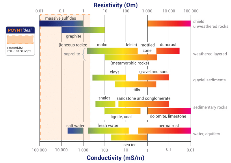
Specified in S/m. See the figure below for typical conductivity values for rock. Note the scale at the bottom is in mS/m.


This is the mean variation of the unevenness of the walls in millimetres.
This is a difficult parameter to estimate. It is the mean tilt of the walls from perpendicular. Typically about 1-2 degrees.
Select the antenna you plan to use at the transmitter. Note that the antennas with “HELI” in the product model name are circularly polarised and the others are all linear polarised. You can investigate the throughput of a link using antennas with different polarisations.
Antenna distance from wall
The distance of the antenna from the left wall of the tunnel in metres (m). Generally, the closer the antenna is to the centre of the tunnel, the better the link quality.
Antenna height above ground
Specified in metres.
Transmit power of the radio in dBm. Note that an Access Point (AP) may have a transmit power of 29dBm at MCS0 but only 25dBm at MCS7.
The frequency specified in this field is the frequency at which you would like to analyse the link. The application only accepts one frequency at a time, so if you want to see what happens at multiple frequencies, you will have to run the application multiple times. If, for example, you wish to see how a Wi-Fi signal propagates down the tunnel, then one typically only needs to specify the frequency in the centre of the band to get a good idea of the propagation characteristics. So, for the 2400-2500 MHz band, choose 2450 MHz as the frequency of operation, and for the 5GHz band, choose 5850 MHz.
Select the antenna you plan to use at the receiver. Please note that the antennas with “HELI” in the product model name are circular polarised and the others are all linear polarised. You can investigate the throughput of a link using antennas with different polarisations.
Antenna distance from wall
The distance of the antenna from the left wall of the tunnel in metres (m). Generally, the closer the antenna is to the centre of the tunnel, the better the link quality.
Antenna height above ground
Specified in metres.
Minimum acceptable received signal strength in dBm. The sensitivity of the receiver can be found in the data sheets. This figure represents the minimum received power where communications is possible.
The link will use the lowest quotation modulation scheme and hence will result in the lowest data throughput. A receive signal strength must be specified that will ensure that the data rate you require is achievable.
For example, an Access Point (AP) may have a minimum received power requirement of -96dBm at MCS0 but as much as -77dBm at MCS7. The data throughput of MCS0 is lower than MCS7, hence the higher received power requirement for MCS7.
Distance down the tunnel between the antennas from the first radio unit to the second unit in metres (m).