Directional Antennas in a Semi-Urban Environment
In this article Pieter Prinsloo highlights the benefits of using Directional Antennas in Semi-Urban environments using a US customer case study. It explains how aligning the POYNTING XPOL-2-5G antenna can improve signal strength and highlights guidelines to follow when installing these antennas.
1. Introduction
This article uses a US based customer’s situation to show the importance of Directional Antennas in a semi-urban environment. Pieter takes the actual tower and residence locations and shows how changing the alignment of the POYNTING XPOL-2-5G antenna can make a significant difference in your signal strength.
UNI-Directional Antennas, works very well in semi-urban areas where distances between Mobile Network Operator’s (MNO) Base Stations tend to be large and sparsely populated. There are however a few guidelines, as far as installing Directional Antennas are concerned, that are important to remember.
When to use a Directional Antenna?
POYNTING Antennas designs and manufactures two main types of Antennas for the LTE, 4G and 5G deployment.
2. OMNI-Directional Antennas
These Antennas are designed mainly for urban areas where multiple Base Stations of a particular MNO (the MNO of your choice) are located, typically within a few hundred yards or meters from the location where the Antenna + the LTE, 4G, 5G Router is to be installed.
The rationale is that the Router which will transmit/receive Signal to/from these Base Stations, will have ample Radio Frequency (RF) Signal from all these Base Stations due to the short distances the RF Signal has to travel.
Typically, the Router will then ‘switch’ between these Base Stations using various techniques employed by MNOs to transmit/receive multiple Signals.
3. Uni-Directional Antennas
In suburban areas one often finds that the MNO Base Stations are placed further apart, 1000+ yards (1000+ meters), often with dense suburban housing/housing complexes and/or lots of plants/trees; all of which contribute to poor signal quality requiring an Antenna with what is known as ‘High Gain’.
Poor Radio Signal ‘Quality’ can either be:
- Low Radio Signal Levels due to longer distances the Signal has to travel.
- Radio Frequency ‘Noise’ [Random Radio Signals] from sources like Electric Grid Transformers, nearby machinery, etc.
- Interference from ‘other’ Radio Sources interfering in the ‘same’ Frequency Band as the desired Radio Signal the Internet Router is trying to receive.
4. How to choose?
A Directional Antenna is designed to overcome the limitations of ‘Poor Radio Signal Quality’ by virtue of:
- The ‘Directionality’ of these Antennas ‘focuses’ the Radio Signal to achieve Higher Gain to overcome Radio Signal losses due to distance from Base Stations.
- ‘Shuts out’ a huge proportion of the ‘Noise’ or ‘Random Radio Signals’ due to this ‘Directionality’ as well as the ‘in Channel’ interference from other Radio Stations.
Many suburban areas suffer from the limitations in 2.2 and 3.1 above and therefore a Directional Antenna such as POYNTING’s XPOL-2-5G is an excellent choice for many suburban areas as proven by many installations worldwide.
5. The DO’s and DON’T’S of installing a Directional Antenna
Let us consider a ‘real life’ scenario – the area and Mobile Network Operator (T-Mobile) are real, the requirement is fictitious but a ‘real life’ scenario, nevertheless.

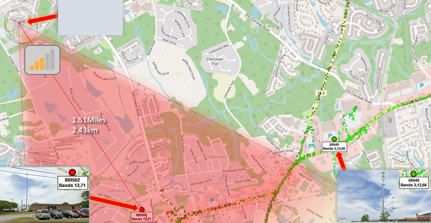
Figure 1 above depicts a real suburban area in the USA; the rectangles show a suburban residence (greyed out), and the two circles encircle two T-Mobile LTE Base Stations operating on:
- eNodeB ID – 889502; Bands 12 (700MHz) and 71 (600MHz)
- eNodeB ID – 69549; Bands 2 (1900MHz), 12 (700MHz), 66 (1700MHz)

Figure 2 shows the distances to these towers from the residence, top left-hand corner.
- Let us assume, for purposes of this exercise, that the lower Frequencies of Bands, 12 (700MHz) and 71 (600MHz) are ideal for transmission from the Base Stations to the area where the residence is located.


- The owner of the residence drives past Base Station eNodeB ID 889502 every day and assumes that this is the correct Base Station to ‘connect to’ and this Base Station supports the Bands 12 and 71.
- Distance to the LTE Base Station of T-Mobile, the owner’s chosen ISP is good at 1.51miles (2.43km).
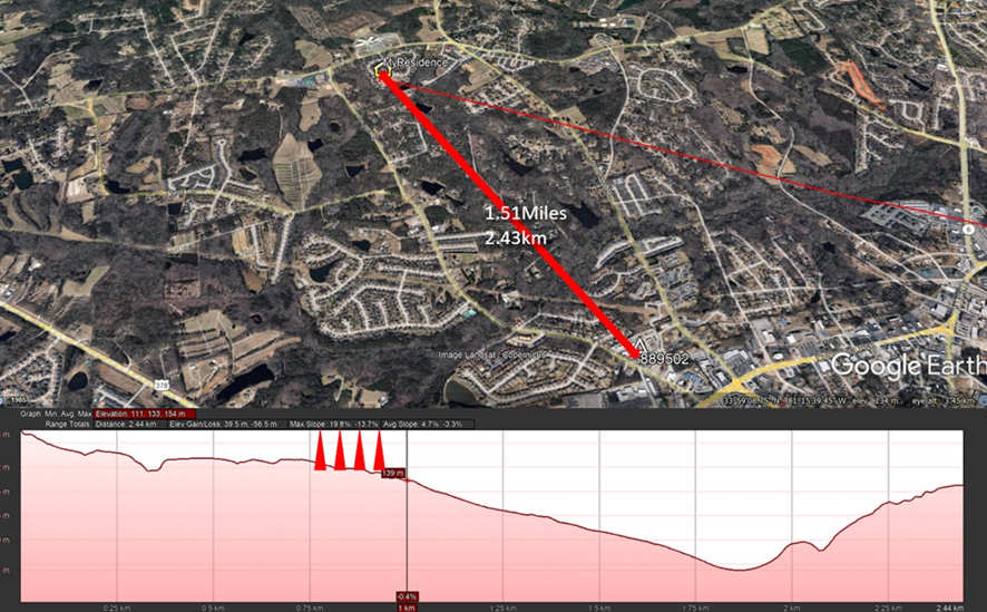
- HOWEVER, the owner (or installer) embarking on this installation, does not realize that there is an obstruction at 820 yds (750m) from his residence; some very high, dense trees blocking the Signal Path towards eNodeB ID 889502 (Figure 3)
- The owner (installer) deploys the XPOL-2-5G as per Figure 4 but gets poor Signal Quality from eNodeB ID 889502 due to the ‘blocking’ of the Radio Signal path by the trees as shown in Figure 3.
- Moreover, the ‘Directionality’ of the Antenna prevents the Signal from Base Station eNodeB ID 69549, (see Figure 4) where the ‘Radiation Pattern’ is such that the Radio Signal from eNodeB ID 69549 does not ‘fall within’ the ‘Aperture’- or ‘Acceptance Angle’ of the XPOL-2-5G.
- Due to the above factors namely bad Radio Path Loss and not being aligned with eNodeB ID 69549, the owner experiences bad Signal levels and subsequently poor Download/Upload performance i.e., a bad user-experience altogether.
A word on Directional Antennas:
- Directional Antennas have the ability to increase the Radio Signal Gain in a particular ‘direction’.
- This is very advantageous when a single Base Station, like in many suburban areas, is the best option; it increases the Radio Signal available to the Router and decreases the amount of Radio ‘Noise’ (‘Spurious Radio Emissions’) and interference from other Radio Networks in the vicinity operating on the same frequencies.
- Figure 5 below shows the ‘Directional’ nature of the Antenna (XPOL-2-5G) at the different Radio Frequencies utilized by the Mobile Network Operators; these ‘Radiation Patterns’ are measured in a special chamber by POYNTING’s Engineers.
- In Figure 4 I have ‘overlayed’ the ‘Radiation Pattern’ on the Map to show how the ‘Acceptance Angle’, directed at eNodeB ID 889502, will be too narrow to accept Signals from eNodeB ID 69549 – the
XPOL-2-5G needs to be ‘directed’ correctly. (See the full ‘Technical Specification’ [T’S] at www.POYNTING.tech).
The Solution
Knowing which Base Station, provided by your ISP/Mobile Network Operator, will provide the best possible Radio Signal, is extremely important. Without this knowledge endless hours can be wasted trying to achieve good reception and performance!
Consider the (installer) owner knowing that:
- There is another eNodeB situated at ID 69549 with ‘High Output Power’.
- The importance of the Acceptance Angle and then directing the Antenna at eNodeB ID 69549.
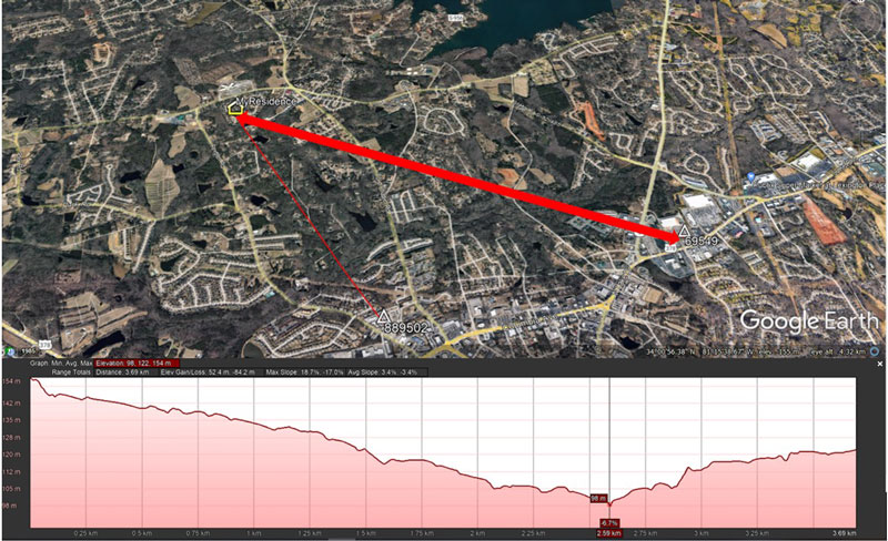
- Figure 6 below depicts the Solution from a correct Antenna orientation point of view for the circumstances presented by this particular installation.


Furthermore, looking at Figure 7, one can see that the topographical path is a lot clearer than the challenging situation with the Radio Signal path towards eNodeB ID 889502
Cable Losses:
- Another serious issue to consider is Cable Losses from Antenna to the Router.
- Consider Figure 8 above, a 15m (50ft) HDF-195 is a good quality cable but it has more RF losses per meter than for instance LMR-400 also shown in Figure 7.
- LMR-400 may be slightly more difficult to install due to its rigidity and bulk but, as you can see from the results table, a 15m (50ft) LMR-400 cable will have a huge advantage providing anywhere from double (2x) to three times (3x) the Signal to the Router due to lower losses between it and the Antenna.
- The POYNTING A-XPOL-0002-V3-12 Model is fitted with N-Type connectors for precisely this reason – installing LMR-400, with N-Type connectors fitted, for these longer ‘cable runs’ required.
The Summary
- Know where and how to point your POYNTING XPOL-2-5G Antenna; height above Mean Ground Level is always a PLUS, mount as high on a pole/mast as is conveniently possible (and observe ‘grounding the Antenna’ rules on very high installations!).
- Keep cables between Antenna and Router as short as possible and consider LMR-400 (or other ‘low loss’ cable) for these longer cable runs.
- IMPORTANT: Some Routers with ‘External’ Antenna ports have an ‘Internal/External Antenna Switch’ that needs to be configured (from the Web Interface ‘Configuration Settings’) before it ‘activates’ these ports for external Antenna deployment.


