FAQ: What Should I Consider When Using Extra Cables & Splitters with MIMO Devices
We had a similar question regarding connecting a 2 x 2 router; HUAWEI B828-263 to external Antennas; question here below.
The customer that asked this has a HUAWEI B818-263 Router which is a 4×4 MIMO router with 2 external antenna connectors. He is worried that connecting a 2×2 MIMO Antenna to the router will give worse performance than not connecting any antenna.
Answer:
The B818-263 router (and many other) unfortunately only has 2×2 MIMO external ports. It is not obvious how the router will respond to the external antennas (maybe they have information in their user manual), but it is possible when connecting the two external ports that the 4×4 MIMO is downgraded to 2×2 MIMO, but it is also possible that they continue to use 4×4 MIMO with two internal antennas and two external antennas.
Connecting an external antenna allows much better signal reception, and more relevantly; better Carrier Signal to Noise Ratio (SNR), thereby improving the overall experience, even if only using 2×2 MIMO. The improvement in internet experience from having a good external antenna on this type of router usually outweighs the benefit of 4×4 MIMO. Peak throughputs may be better with 4×4 MIMO vs 2×2 MIMO, but the overall stability of the connection and overall experience should be much better with the implementation of an external antenna, e.g. our XPOL-2-5G antenna. You are welcome to have a look at our webinar titled: “Taking Fixed Wireless Access (FWA) from bits to Bytes” which has a section covering external antenna benefits.
If the router does support 4×4 MIMO with two internal router antennas and two external antennas, then the use of an external antenna will be even more beneficial.
Expanded Answer:
The first question one needs to ask when considering connecting 4 x 4 MIMO is, what does one want to achieve? Connecting 4 x 4 is normally considered to create either full 4 x 4 (mainly LTE-Advanced and 5G) with 4 x Carrier aggregation transmission/reception or alternatively space diverse reception.
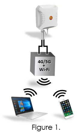
Normally, as per the first question above, the two external ports on the router are connected as per the diagram on the left. This is known as ‘cross polarization’ and will improve the Signal-to-Noise-Ratio substantially over two aggregated data streams received by the router thus improving the RSRP, RSRQ and SINR.
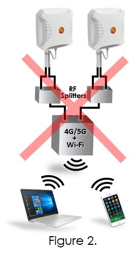
The connection on the right will provide ‘space diversity’ which works well when one finds oneself in a densely populated area where the signal is influenced by multipath fading which consist of reflection (smooth surfaces), scattering (rough surfaces), diffraction (edges of buildings etc.) and refraction (atmospheric layers).
These factors can be mitigated by placing antennas ‘spatially diverse’ (apart) to compensate for variances in signal ‘arrival’ whilst at the same time capitalize on the multidimensional nature of MIMO transmitted/received signals.
HOWEVER – there are two ‘buts’ to consider and they are BIG buts:
1. Cable Losses:
The XPOL-2-5G can be quotationed with either 5m or 10m HDF-195 cable or with N-Type connectors. For cable lengths longer than 10m as well as instances where the receiving antenna/tower distances are a challenge one should consider N-type connectors and using low loss cable like LMR-400; compare the results of having to use a 15m cable run to the router and the effect on net gain.
The table below allows for a 1m cable between the antenna and the splitter. The calculation excludes possible connector losses, it is therefore imperative that good quality connectors and good installation procedures be used when ‘making up’ the cables.


2. RF Splitters:
It should be noted that we do not recommend Passive RF splitters normally. These devices should only be used a ‘last resort’ and then also just in special cases described below.
RF Splitters ‘loses’ 3dB port-to-port of the RF signal. Therefore, this type of setup will only improve data throughput when the received signal is strong (it must overcome a 3dB ‘deficit’ in the splitter) and, can only benefit performance if reception is impaired mainly due to multipath fading (as mentioned above, indicated by mostly densely populated areas with multiple reflection/refractions) and the RF signal from a single cross-polarized antenna experiences poor throughput.
However, the bigger challenge with RF Splitters are unwanted intermodulation products. For MIMO the two signals on port 1 and port 2 of the Router are purposefully decorrelated to minimize intermodulation products from being radiated from one Dipole to the other.
Therefore, the correct connection, if the bigger problem was Multipath Fading rather than Signal Strength, and one would want to create Space Diversity on only two router ports, then consider the connection as per Figure 3, this figure shows the physical connections if one connects the Splitters like the connections shown in Figure 3.
Again, really only worthwhile if the signal is strong enough to overcome the splitter losses and the main signal losses are due to multipath fading mentioned above


Conclusion:
Directional antennas such as the XPOL-2-5G are typically used where a single base station/tower is the primary source for a Fixed Wireless Access (FWA) connection. The topography viz-a-viz buildings, vegetation, hills etc. are typically problematic causing the multipath fading mentioned above.
Therefore, the configuration/installation as per Figures 3. and 4. Should be carefully considered in highly populated areas where a very strong signal is present but Multipath fading is problematic; the Antenna should be at least 60cm apart.
The table below highlights the Splitter loss dilemma; as you can see net Gain through Cable losses coupled with Splitter loss is significant.
Please note that POYNTING will be releasing our own, high quality, ultra-wideband (400 – 7200 MHz) splitter in the near future. You can find more information by searching for SPLT-16 on our website from March 2021.


